If you’ve ever stood next to an electric furnace transformer during a melt, you’d feel it before you see it: a low, constant hum, a faint vibration through the concrete pad, and the quiet certainty that every part of this piece of equipment is working at the edge of what it was designed to do. As someone who’s spent the last 12 years as part of a team that builds, tests, and troubleshoots these transformers for steel mills, foundries, and mining operations, I can tell you that thermal stress is the silent culprit behind most unplanned outages and premature component failure here. It’s not just a theoretical engineering problem—when your furnace goes down mid-heat, you’re losing thousands of dollars an hour, and that’s before you even factor in repair costs. Electric Furnace Transformer
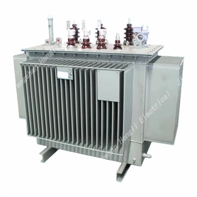
A few years back, we had a customer in the Midwest come to us with a problem: their 15 MVA electric furnace transformer was failing every 18 months, while our standard units lasted twice that long. Their maintenance team had been replacing the windings every time, but the failures kept happening near the top of the high-voltage winding, where the temperature readings from their sensors seemed fine on paper. When we ran a full thermal analysis on their unit—something their original supplier had never done—we found that the hot spot temperature was 45 degrees Celsius higher than their rated limit, caused by uneven airflow around the core and a poorly sized radiators. That’s the thing about thermal stress in these transformers: it’s rarely uniform. It hides in gaps between cooling fins, in the layers of a winding, at the points where leads connect to the bushing. You can’t just look at average oil temperature and call it a day.
Today, I want to walk through how we analyze that thermal stress— the process we use every time we design a new transformer, troubleshoot a failing one, or help a customer optimize their existing unit. This isn’t just textbook stuff; it’s the lessons we’ve learned from fixing 70+ transformers that other suppliers wrote off as “too far gone.”
First, let’s ground this in why electric furnace transformers are different from every other type of power transformer. Regular power transformers run at a relatively steady load, with minimal fluctuations, day in and day out. Electric furnace transformers? They’re subject to cyclic, nonlinear loads that swing from 20% of rated capacity to 120% and back again in a matter of seconds. When you’re melting scrap metal, the arc isn’t stable—it flickers, jumps, and shifts, which means the current through the windings spikes and drops constantly. That rapid change in current generates heat unevenly across the core, windings, and insulation system, creating thermal stress that cycles thousands of times a day. Over time, that stress breaks down the insulation, expands and contracts metal parts, and eventually leads to failure. The first step to analyzing it is to stop treating the transformer like a static device and start treating it like a system that’s in constant, dynamic motion.
The first stage of our analysis is data collection, and not just from the built-in temperature sensors. Too often, customers rely on the two or three thermocouples the original supplier installed on the outer tank, which only tell you what’s happening at the surface. We start with on-site data logging for 72 hours straight—long enough to capture a full melt cycle, from charging scrap to tapping molten metal. We place 12 to 16 additional sensors: one inside the top of the high-voltage winding, one in the low-voltage winding near the core, one between every other cooling fin, one at each bushing connection, and one at the bottom of the oil tank. We also measure ambient temperature, humidity, and the airflow around the transformer—things most teams ignore until it’s too late.
A few months ago, a foundry in Ohio called us because their transformer was leaking oil through the welds on the tank. The maintenance team blamed old age, but when we brought our data loggers, we found that the transformer was running at 115% load every night during their night shift melt, and the airflow from their cooling fans was only 40% of the rated level. The temperature data showed that the outer tank was hitting 102 degrees Celsius at its hottest point, while the oil inside was only 78 degrees. That meant the metal of the tank was expanding and contracting 24 degrees every 8 hours, from the hot outer surface to the cooler inner oil. Over 5 years, that cyclic expansion had fatigued the welds, leading to leaks. If we’d only used the tank sensors, we would have never found the root cause—we would have just replaced the tank and waited for another leak.
Once we have that data, the next step is to model the thermal behavior using finite element analysis (FEA), but not the generic FEA models you’d use for a residential transformer. We build custom models that account for the specific load profile of electric furnace applications, the type of insulation we use (we use Nomex paper for our windings, which has a higher temperature rating than standard kraft paper), and even the material of the tank and cooling fins. The key here is mapping hot spots—those localized areas where the temperature spikes much higher than the average.
Let’s talk about windings, because that’s where 60% of electric furnace transformer failures start. The windings are made of copper or aluminum conductors, layered on top of each other, with insulation in between. When current flows through them, each conductor generates resistance heat, but the heat can’t escape evenly from the inside of the winding stack. If you have a winding that’s 2 meters tall, the top of it will always run hotter than the bottom, because the hot air rises and gets trapped at the top. In some cases, we’ve seen hot spots in the middle of the winding, where two conductors with higher resistivity are next to each other, or where a layer of insulation is slightly thinner, slowing heat transfer. The FEA model we run doesn’t just calculate average winding temperature—it calculates the temperature at every 1cm section of every layer. That’s the only way to spot those hidden hot spots.
We also look at the interaction between thermal stress and mechanical stress, which is a part most people miss. When metal gets hot, it expands; when it cools, it contracts. For a transformer winding, that means every time the load changes, the conductor moves slightly. Over thousands of cycles, that movement wears down the insulation, leading to small gaps where heat can’t escape, which makes the problem worse. We recently had a customer whose transformer had a winding short circuit that no one could explain. When we analyzed the thermal-mechanical model, we found that the cyclic expansion and contraction of the winding had caused the top layer to rub against the next layer down, wearing through the insulation over 3 years until a short occurred. The electrical testing had shown no signs of a short until it happened, but the thermal analysis gave us a clear picture of the slow, steady damage that had been building.
Cooling system analysis is another big piece of the puzzle, and one that’s often overlooked. Most electric furnace transformers use either natural oil cooling (ONAN) or forced oil cooling (OFAF). But the size of the radiators, the number of fans, and the placement of the cooling units relative to the furnace itself all affect thermal performance. Furnaces generate a lot of ambient heat—if your transformer is mounted 10 meters from the furnace, that’s different from if it’s mounted 2 meters away, where the furnace’s radiated heat adds to the transformer’s internal temperature. A few years back, a steel mill in Pennsylvania relocated their transformer to save space, moving it 3 meters closer to the electric arc furnace. Within 6 months, their transformer’s hot spot temperature had jumped by 30 degrees Celsius. We did a thermal mapping of the area and found that the furnace was adding 15 degrees to the ambient temperature around the transformer, and their existing radiators were sized for their previous location. Adjusting the fan speed and adding two extra cooling fins brought the hot spot back within limits, and the failure rate dropped to zero.
Once we’ve collected the data, modeled the heat flow, and identified the hot spots, the next step is to quantify the damage. The industry standard says that the maximum temperature for Class A insulation (standard kraft paper) is 105 degrees Celsius, with a 6-degree Celsius limit for cyclic stress. Wait times a degree above that, you reduce the insulation’s life by half. For our transformers, we use Class F insulation, which has a rating of 155 degrees Celsius, and we design for a maximum hot spot of 130 degrees Celsius, with a 5-degree cyclic limit. That doesn’t just mean we’re safer—we designed our cooling systems and winding layouts to keep the hot spot exactly where it needs to be, even during the peak load spikes that come with a heavy melt. We also factor in the customer’s specific operating cycle: if they run 12-hour day shifts and 8-hour night shifts, our thermal model adjusts to match that, so we’re not over-sizing or under-sizing for their actual use.
The last part of our analysis is preventative action. It’s not enough to just tell a customer where their thermal stress is coming from—we give them a clear plan to fix it. That could be adjusting their load cycles, adding extra cooling, reconfiguring the windings, or even replacing old insulation. For the customer in the Midwest I mentioned earlier, we didn’t just fix their radiator size; we worked with their maintenance team to set up a monthly thermal scan of their transformer, focusing on the hot spot we identified, and we adjusted their operating schedule to reduce peak loads by 10% during their hottest summer months. Their transformer is still running 10 years later, with no failures.
Here’s the thing: when it comes to electric furnace transformers, thermal stress isn’t a problem you can ignore. It doesn’t show up as a warning light or a loud noise until it’s almost too late. It’s the small, repeated cycles of heat and cooling that wear down every part of the machine, until one day you’re staring at a mid-heat outage that costs you $10,000 an hour or more. The process we use to analyze it is about getting past the surface numbers, digging into the way the transformer actually works in your specific environment, and making sure every part is designed and maintained to handle the stress it will face.
As a supplier, our job isn’t just to sell you a transformer. It’s to make sure that transformer works for you, day in and day out, through every melt, every load spike, and every seasonal temperature change. If you’re dealing with unplanned outages, unexpected repairs, or transformers that don’t last as long as they should, we can walk you through our full thermal analysis process—on-site data collection, custom modeling, and a clear plan to get your equipment back on track. No generic solutions, no one-size-fits-all models, just hands-on experience from decades in the industry.
If you’re ready to stop guessing about your transformer’s thermal performance and start preventing downtime, reach out to us to discuss your specific application.
Electric Furnace Transformer References:
IEEE Std C57.12.90, Standard Test Code for Liquid-Immersed Distribution, Power, and Regulating Transformers
NEMA Standard TP 1, Thermal Evaluation of Liquid-Immersed Power Transformers
ASME Boiler and Pressure Vessel Code, Section VIII, Division 1, Rules for Construction of Pressure Vessels
Zhejiang Jiangshan Hengli Electrical Co., Ltd.
Zhejiang Jiangshan Hengli Electrical Co., Ltd. is one of the most professional electric furnace transformer manufacturers and suppliers in China, featured by quality products and low price. Please rest assured to wholesale cheap electric furnace transformer in stock here and get pricelist from our factory. Customized orders are welcome.
Address: 212 Fuzhu Street Sidu Town, Jiangshan, Zhejiang, China
E-mail: henglijs@foxmail.com
WebSite: https://www.henlypower.com/
